
Misinterpreting surge arrester ratings is one of the most common causes of under-protection and premature arrester failure.
Table of Contents
Key Points: What You’ll Learn
- MCOV is the most fundamental rating — exceeding it even slightly causes gradual thermal runaway that may take months or years to manifest; always calculate MCOV including voltage tolerance (+5%) and system unbalance (+10%).
- Oversizing the rated voltage is as dangerous as undersizing — a higher-rated arrester produces higher residual voltage, reducing the protective margin below the 20% minimum and leaving equipment under-protected.
- TOV capability must be coordinated with actual system temporary overvoltage duration — selecting a 10-second TOV rating when the system TOV lasts 30+ seconds causes delayed post-fault arrester failure.
- Correct arrester selection follows a systematic five-step process: calculate system MCOV → coordinate TOV → verify energy absorption → confirm insulation coordination margin ≥ 20% → verify pressure relief rating.
- IEC 60099-4 and IEEE C62.11 use different terminology, rating ratios, and energy classification systems for the same physical device — never assume cross-standard equivalence without verifying through manufacturer type test reports.
1. The Four Critical Electrical Ratings and What They Mean
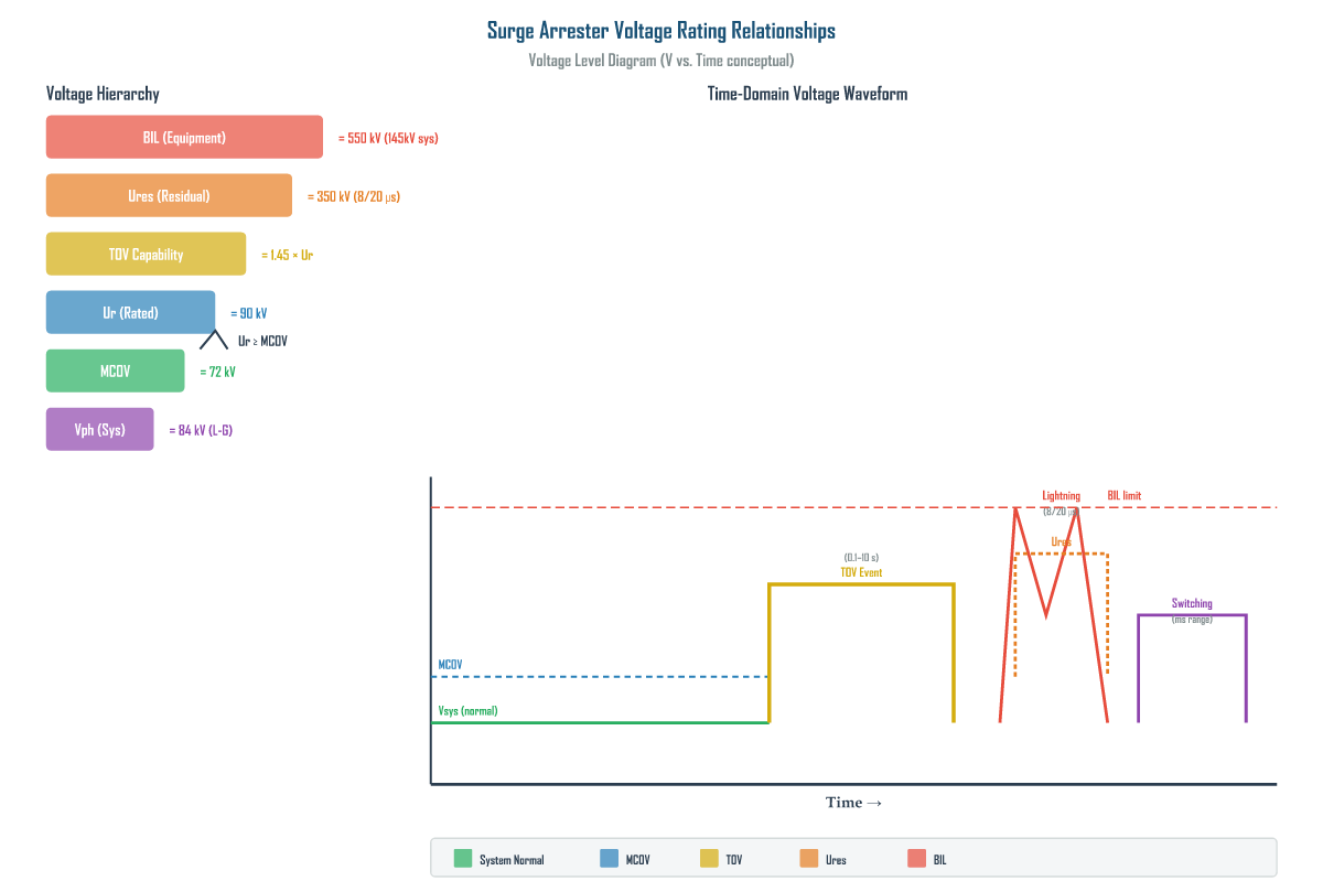
The four most important electrical ratings of a metal-oxide surge arrester define the voltage and energy limits within which the device can operate safely without degradation or failure. Each rating addresses a different aspect of the arrester’s interaction with the power system, and all four must be understood together to select the correct arrester for any application.
MCOV (Maximum Continuous Operating Voltage)
MCOV is the maximum rms value of power-frequency voltage that may be applied continuously between the arrester terminals without causing thermal runaway. This is the most fundamental rating — exceeding MCOV, even by a small margin and for an extended period, will cause the arrester to fail.
MCOV is determined by the inherent V-I characteristics of the ZnO varistor blocks. At voltages below MCOV, the leakage current is dominated by the capacitive component, and the resistive component is small (typically less than 1–2 mA for station-class arresters). As the voltage approaches MCOV, the resistive component begins to increase rapidly, approaching the thermal instability threshold.
Rated Voltage (Ur)
The rated voltage is the reference voltage for which all other arrester characteristics — residual voltage, TOV capability, energy absorption — are specified. Per IEC 60099-4, the rated voltage must be equal to or greater than MCOV. In IEC-standard arresters, the ratio of rated voltage to MCOV is typically 1.25 to 1.35 for station-class and 1.2 to 1.3 for distribution-class arresters.
TOV (Temporary Overvoltage Capability)
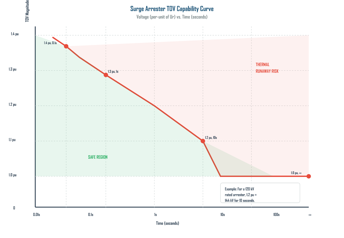
TOV capability defines the arrester’s ability to withstand sustained overvoltages lasting from a few cycles to several seconds without thermal runaway. TOV events are caused by single-line-to-ground faults, load rejection, ferroresonance, and loss of load with generation. IEC 60099-4 requires arresters to withstand at least 1.0 pu indefinitely, 1.2 pu for 10 seconds, and 1.3 pu for 1 second.
Energy Absorption Capability
Energy absorption capability defines the maximum surge energy the arrester can dissipate without damage, expressed in kJ/kV of rated voltage. IEC 60099-4 defines energy classes from 1 kJ/kV to 20 kJ/kV. The class is determined by the high-current discharge test (4/10 µs waveform, 2 shots at 65 kA or 100 kA depending on class).
2. Why Getting Each Rating Right Determines System Protection Reliability
Each rating serves as a critical boundary — and misjudging any one of them creates a specific failure mode. The consequences of rating errors are not theoretical; they manifest as transformer failures, arrester explosions, and widespread outages in real power systems.
MCOV Errors: The Silent Killer
If the system’s maximum continuous line-to-ground voltage exceeds the arrester’s MCOV, the arrester enters a gradual thermal runaway. The resistive leakage current increases continuously, generating heat that cannot be dissipated. This is particularly dangerous because the failure may take months or years to manifest — the arrester appears to function normally until the internal temperature crosses the instability threshold.
For effectively grounded systems (grounding factor < 1.4), the maximum continuous L-G voltage is calculated as:
VL-G,max = VLL / √3 × 1.05 (tolerance) × 1.10 (unbalance, if applicable)
For ungrounded or high-resistance-grounded systems, the line-to-ground voltage during a single-line-to-ground fault can rise to nearly the line-to-line voltage. In such systems, the arrester MCOV must be selected based on the line-to-line voltage, not the line-to-ground voltage — a common mistake that leads to rapid arrester failure.
Rated Voltage Errors: The Oversizing Trap
Selecting an arrester with a rated voltage that is too low risks thermal runaway during continuous or temporary overvoltage conditions. But oversizing — selecting too high a rated voltage — is equally problematic. A higher-rated arrester has a higher residual voltage (Ures), which reduces the protection margin for the insulated equipment.
Important: The goal is to select the lowest rated voltage that satisfies all continuous and temporary overvoltage requirements. An oversized arrester will not fail from overvoltage, but it may allow the protected equipment to be damaged because the residual voltage exceeds the equipment’s withstand capability.
TOV Capability Errors: The Post-Fault Failure
TOV capability must be coordinated with system temporary overvoltage studies. A common error is selecting an arrester with a 10-second TOV rating when the actual system TOV lasts 30 seconds or longer. The arrester may survive the initial fault but fail thermally during the extended TOV — often minutes after the protective relay has cleared the fault, making the failure appear inexplicable.
The TOV capability curve is approximately hyperbolic: higher overvoltages can only be tolerated for shorter durations. Operating above the curve risks thermal runaway.
Energy Absorption Errors: The Catastrophic Rupture
When the arrester’s energy absorption capability is exceeded — typically during high-energy switching surges or multiple lightning strikes — the ZnO blocks can crack, melt, or suffer puncture. This failure mode is sudden and often catastrophic, resulting in housing rupture. Energy overstress is particularly common in arresters protecting capacitor banks and in areas with high ground flash density.
| Energy Class (kJ/kV) | Typical Application | 4/10 µs Discharge Current | Typical System Voltage |
|---|---|---|---|
| 1–2 | Distribution lines, moderate lightning areas | 40–65 kA | 1–36 kV |
| 3–5 | Subtransmission, moderate switching surges | 65–100 kA | 33–145 kV |
| 5–10 | Transmission lines, capacitor bank protection | 100 kA | 145–400 kV |
| 10–20 | EHV/UHV lines, very high lightning density | 100–150 kA | 400–800 kV |
3. How to Apply Ratings When Selecting an Arrester for Your System
Selecting the correct arrester requires a systematic five-step process that coordinates each rating with the system’s actual operating conditions. Skipping any step risks either premature arrester failure or inadequate equipment protection.
Step 1: Determine the System MCOV Requirement
Calculate the maximum continuous line-to-ground voltage, including voltage regulation tolerance (typically +5%) and expected unbalance (up to +10% for some networks). For effectively grounded systems, use VLL/√3. For ungrounded systems, use VLL directly. The arrester’s MCOV must exceed this calculated value.
| System Voltage (kV LL) | Grounding Type | Max Continuous L-G (kV) | Required MCOV (kV) | Typical Rated Voltage (kV) |
|---|---|---|---|---|
| 15 | Effectively grounded | 9.2 | 10 | 12 |
| 33 | Effectively grounded | 20.2 | 22 | 27 |
| 72.5 | Effectively grounded | 44.3 | 48 | 60 |
| 145 | Effectively grounded | 88.6 | 96 | 120 |
| 245 | Effectively grounded | 149.7 | 162 | 198 |
| 420 | Effectively grounded | 256.6 | 278 | 336 |
| 15 | Ungrounded | 15.0 | 16 | 18 |
| 33 | Ungrounded | 33.0 | 36 | 39 |
Step 2: Select Rated Voltage Based on TOV Coordination
Conduct system temporary overvoltage studies to determine the worst-case TOV magnitude and duration. Compare these values against the arrester’s TOV capability curve (as shown in Figure 2). The TOV point must fall within the safe region. If the system TOV exceeds the standard curve, a higher-rated arrester or a specially designed high-TOV arrester must be selected.
Step 3: Verify Energy Absorption Against Expected Surge Exposure
Determine the expected surge energy based on:
- Lightning flash density: Areas with > 10 ground flashes/km²/year require energy class 5+ kJ/kV.
- Switching surge energy: For capacitor banks, calculate the stored energy (½CV²) and select an arrester that can absorb at least 2× this value.
- Line length and configuration: Long lines in high lightning areas accumulate multiple strikes — higher energy class is justified.
Step 4: Verify Insulation Coordination
Check that the arrester’s residual voltage at the specified discharge current provides adequate protection margin for the equipment’s basic insulation level (BIL). The protective margin should be at least 20%:
Protective Margin = (BIL − Ures) / BIL × 100% ≥ 20%
If the margin is insufficient, either select an arrester with lower residual voltage (which may require a lower rated voltage) or upgrade the equipment insulation level.
Step 5: Verify Pressure Relief Rating
The pressure relief rating must be compatible with the available fault current at the arrester location. For station-class arresters, typical ratings are 40 kA, 63 kA, or 80 kA rms symmetrical. Consult the short-circuit study to ensure the arrester can safely vent internal pressure without fragmenting during an internal fault. This is particularly critical in GIS and indoor substations where fragmentation can cause extensive secondary damage.
Selection Summary: The correct arrester is the one with the lowest rated voltage that satisfies MCOV, TOV, energy, and pressure relief requirements — while still providing adequate protective margin (≥ 20%) for the equipment BIL. Never oversize “for safety” — it reduces protection. Never undersize to save cost — it causes failure.
4. IEC 60099-4 vs. IEEE C62.11 Rating Systems: Key Differences Engineers Must Know
Two major standards govern surge arrester ratings worldwide: IEC 60099-4 (used in most of the world) and IEEE C62.11 (used primarily in North America). While both cover metal-oxide surge arresters, they define ratings differently, use different terminology, and have different test procedures. Engineers working on international projects must understand these differences to avoid specification errors.
| Aspect | IEC 60099-4 | IEEE C62.11 |
|---|---|---|
| Primary Standard Region | International (Europe, Asia, Africa, most of world) | North America (USA, Canada, parts of Mexico) |
| Reference Voltage | Rated Voltage (Ur) — explicitly defined as the reference for all characteristics | Duty-Cycle Voltage — the reference voltage; “Rated Voltage” term is not used the same way |
| MCOV Definition | MCOV is specified separately, with Ur typically 1.25–1.35 × MCOV | MCOV is the primary continuous voltage rating; duty-cycle voltage ≈ 1.25 × MCOV (similar ratio but different terminology) |
| TOV Capability | Explicit TOV capability curve required; standard values: 1.2 pu/10s, 1.3 pu/1s | TOV capability specified via “Temporary Overvoltage” test at specific multipliers; curve format differs |
| Energy Classification | Energy class in kJ/kV of Ur (Class 1–20 kJ/kV); high-current impulse test 4/10 µs at 65 or 100 kA | Energy capability tested via “Transmission Line Discharge” (TLD) class (1–5) rather than explicit kJ/kV; also uses 4/10 µs impulse |
| Discharge Current Classes | 1 kA, 5 kA, 10 kA, 20 kA (nominal discharge current In) | 1 kA, 5 kA, 10 kA, 15 kA, 20 kA (with different test duty cycles) |
| Pressure Relief Test | Specified symmetrical current in kA rms; duration 0.2 s | Similar approach but different test current values and duration specifications |
| Pollution Classification | References IEC 60815 for creepage distance; specific pollution levels I–IV | Uses contamination severity classes; references IEEE Std 1313 for insulation coordination |
| Residual Voltage Test | Measured at nominal discharge current (8/20 µs) and steep current (1/10 µs or 30/60 µs) | Measured at similar waveforms but with different standard current magnitudes for each class |
| Typical Ur/MCOV Ratio | 1.25–1.35 (station class); 1.20–1.30 (distribution) | Duty-cycle/MCOV ≈ 1.20–1.25 (generally tighter ratio) |
| Marking Requirements | Nameplate must show Ur, MCOV, In, energy class, pressure relief class | Nameplate must show duty-cycle voltage, MCOV, nominal discharge current, TLD class |
When procuring arresters for international projects, the key risk is assuming that an “equivalent” rating in one standard provides the same protection in the other. The Ur/MCOV ratio differs, the energy classification systems are not directly comparable, and the test procedures yield different residual voltage values for nominally equivalent arresters. Always specify the standard explicitly and verify cross-standard equivalence through the manufacturer’s type test reports.
5. Summary
- Pain point: Misinterpreting surge arrester ratings is one of the most common causes of under-protection and premature arrester failure — each rating error creates a specific, predictable failure mode.
- Finding 1: The four critical ratings — MCOV, rated voltage (Ur), TOV capability, and energy absorption — define interlocking boundaries. MCOV prevents thermal runaway under continuous voltage; Ur sets the reference; TOV handles fault-induced overvoltages; energy class defines surge withstand.
- Finding 2: Oversizing the rated voltage is as dangerous as undersizing — a higher-rated arrester produces higher residual voltage, reducing the protective margin below the 20% minimum. The correct selection is the lowest rated voltage satisfying all constraints.
- Finding 3: Proper selection follows a five-step process: (1) calculate system MCOV, (2) coordinate TOV capability with system studies, (3) verify energy class against surge exposure, (4) confirm insulation coordination margin ≥ 20%, (5) verify pressure relief against fault current.
- Comparison conclusion: IEC 60099-4 and IEEE C62.11 use different terminology, rating ratios, and energy classification systems for the same physical device. Engineers on international projects must specify the standard explicitly and verify cross-standard equivalence — assuming “equivalent” ratings can lead to both under-protection and unnecessary failure.
Get Your Custom Surge Arrester Solution
Need help selecting the right arrester ratings for your system? Our engineering team provides free technical consultation including system study review and custom rating recommendations.
Or visit www.xin-neng.com to browse our full product catalog.
About Xin-Neng Electric
Xin-Neng Electric is a leading manufacturer of high-voltage electrical equipment, specializing in surge arresters, drop-out fuse cutouts, and composite insulators for power transmission and distribution systems worldwide.
Contact: xn@xin-neng.com | www.xin-neng.com
Frequently Asked Questions
What are the four critical electrical ratings of a surge arrester?
MCOV (maximum continuous operating voltage), rated voltage, TOV capability (temporary overvoltage), and energy absorption (kJ/kV or total kJ). Each governs a different aspect of protection reliability.
Why is getting each rating right important?
Underrating any parameter risks thermal runaway or failure during disturbances, while overrating unnecessarily raises the protective level and cost. Correct matching keeps the equipment BIL respected.
How do I apply arrester ratings when selecting for my system?
Match MCOV to system voltage, set rated voltage with TOV margin, and size energy absorption for the expected surge duty (lightning vs. switching).
What is the key difference between IEC 60099-4 and IEEE C62.11 rating systems?
IEC uses station/intermediate/distribution classes with defined protective levels, while IEEE C62.11 uses duty-cycle ratings and pressure-relief classes. Engineers must convert carefully when bridging the two systems.