
Lightning strikes that reach substation equipment unimpeded can destroy transformers worth millions of dollars in a single event.
Table of Contents
- 1. How Lightning Threatens Substation Equipment and Why Arresters Are Essential
- 2. Why Arrester Location and Protection Distance Are As Critical As Arrester Rating
- 3. Optimal Arrester Placement Strategies for Different Substation Configurations
- 4. Station-Class vs. Intermediate vs. Distribution Arresters: Choosing the Right Protection Level
- 5. Summary
Key Points: What You’ll Learn
- Insulation coordination requires the arrester residual voltage to be below the equipment BIL with at least 20% protective margin — this is the foundation of substation lightning protection design.
- Separation distance between arrester and protected equipment is as critical as arrester rating — inductive voltage drop and traveling wave reflection can add 10–20% voltage overshoot at equipment terminals.
- Every substation needs dedicated arresters at line entrance (LA1), transformer (LA3), and busbar (LA2) — never rely on a single arrester set to protect multiple zones.
- Station-class arresters (10 kA or 20 kA rating) are mandatory for substation applications — intermediate and distribution-class arresters lack adequate energy absorption and protective margin.
- Back-flashover prevention requires coordinated shielding design (angle < 30°) and low tower footing resistance (< 10 Ω) to complete the protection chain.
1. How Lightning Threatens Substation Equipment and Why Arresters Are Essential
Substations house transformers, circuit breakers, disconnectors, and busbars—assets representing extremely high capital investment. Protecting these assets from lightning overvoltages is among the most important functions of a substation design engineer. When a lightning strike hits an incoming transmission line or the substation structure, the resulting surge travels along conductors and can reach voltages that exceed the basic insulation level (BIL) of the equipment. The surge arrester, when properly placed and selected, limits the voltage seen by the equipment to a safe level.
The Insulation Coordination Principle
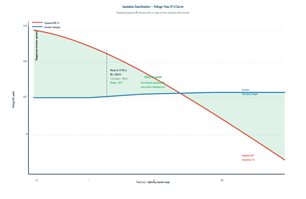
Insulation coordination is the process of selecting equipment insulation strength and surge arrester characteristics so that the equipment is protected from overvoltages at minimum cost. The fundamental principle is straightforward:
Core principle: The protective characteristic of the surge arrester (residual voltage) must be lower than the BIL of the protected equipment, with an adequate margin. The protective margin is defined as (BIL − Maximum Arrester Discharge Voltage) / BIL × 100%. A margin of at least 20% is recommended for critical equipment such as power transformers.
Basic Insulation Level (BIL) Reference Values
BIL is a standardized impulse withstand voltage specifying the peak voltage of a 1.2/50 µs standard lightning impulse that the equipment can withstand without insulation breakdown. Common BIL values include:
- 15 kV system: BIL = 95 kV (minimum)
- 33 kV system: BIL = 200 kV
- 72.5 kV system: BIL = 350 kV
- 145 kV system: BIL = 550 kV or 650 kV
- 245 kV system: BIL = 900 kV or 1050 kV
- 420 kV system: BIL = 1425 kV or 1550 kV
What Happens When Protection Fails
Without adequate surge arrester protection, a direct or nearby lightning strike can cause:
- Transformer failure: Lightning overvoltage can puncture the transformer winding insulation, causing inter-turn short circuits or core damage. Repair is rarely economical; full replacement is typical.
- Busbar flashover: Overvoltage traveling along the busbar can cause air-insulation breakdown, creating a phase-to-ground or phase-to-phase fault requiring immediate outage and cleanup.
- Circuit breaker damage: While circuit breakers are designed to interrupt fault currents, they are not designed to withstand lightning overvoltages repeatedly. Insulation breakdown in the breaker interrupting chamber can lead to catastrophic failure.
- Instrument transformer failure: Current transformers (CTs) and voltage transformers (VTs) have lower BILs than power transformers and are particularly vulnerable to inadequately protected lightning surges.
2. Why Arrester Location and Protection Distance Are As Critical As Arrester Rating
Even a perfectly rated surge arrester cannot protect equipment if it is placed too far away. The protection distance—the physical distance between the arrester and the equipment being protected—directly determines protection effectiveness due to two physical phenomena.
Inductive Voltage Drop Along the Connecting Conductor
The voltage at the protected equipment (Vequipment) is the sum of the arrester’s residual voltage and the inductive voltage drop along the connecting conductor:
Vequipment = Varrester (residual) + L × dI/dt + Vreflected
Where L is the inductance per unit length of the connecting conductor (≈ 1 µH/m), and dI/dt is the rate of rise of the surge current. For a 2-meter lead with dI/dt = 10 kA/µs, the voltage drop is 20 kV. While this may seem small compared to BIL, in modern high-BIL equipment every kV counts toward the protective margin.
Traveling Wave Reflection Effects
When a surge travels along a conductor, it reflects at impedance discontinuities such as equipment terminals. If the separation distance is a significant fraction of the surge wavelength (≈ 300 m for a 1 µs rise time), the reflected wave can add to or subtract from the incident wave, creating a voltage overshoot at the equipment terminals. The worst-case overshoot can add 10–20% to the voltage at the equipment terminals.
Critical design rule: The separation distance should be minimized for every arrester placement. For 145 kV systems, keep the separation distance under 40 m. For 420 kV systems, keep it under 60 m. If the physical layout requires a longer distance, install additional arresters closer to the equipment.
Protection Distance vs. BIL Margin Table
The following table provides guidance on maximum separation distances for adequate protection across different voltage classes:
| System Voltage (kV) | Equipment BIL (kV) | Max. Separation Distance | Arrester Residual Voltage (10 kA) | Protective Margin (%) |
|---|---|---|---|---|
| 15 | 95 | 15 m | 48 kV | 49% |
| 33 | 200 | 25 m | 102 kV | 49% |
| 72.5 | 350 | 30 m | 205 kV | 41% |
| 145 | 550 | 40 m | 310 kV | 44% |
| 245 | 900 | 50 m | 510 kV | 43% |
| 420 | 1425 | 60 m | 850 kV | 40% |
Table 1: Protection distances vs. BIL margins for different voltage classes.
Back-Flashover Prevention: Completing the Protection Chain
Back-flashover occurs when a lightning strike to the shielding system causes the tower potential to rise to a level where line insulation breaks down, introducing very high overvoltages into the substation. Preventing back-flashover requires coordinated shielding design and low grounding resistance:
- Shielding angle: The angle between the vertical and the line from the shield wire to the outer phase conductor should be less than 30° for important lines. For UHV lines, 0–15° is recommended.
- Tower footing resistance: Should be < 10 Ω (preferably < 5 Ω) to minimize ground potential rise during lightning strokes. The tower potential rise is Vtower = Istroke × Rf; keeping this below the critical flashover voltage (CFO) prevents back-flashover.
- Arrester coordination with shielding: Even with good shielding, some strokes bypass the shield wire. The surge arresters at the substation entrance must have sufficient energy absorption capability to discharge these stroke currents without failure.
3. Optimal Arrester Placement Strategies for Different Substation Configurations
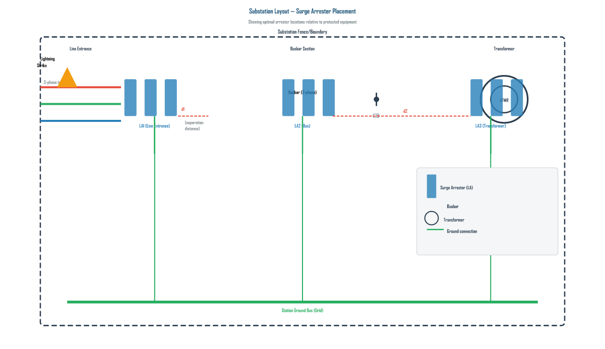
The physical layout of the substation dictates arrester placement strategy. The governing principle is always: place the arrester as close as physically possible to the equipment being protected.
Line Entrance Placement (LA1)
Every incoming transmission line should have a dedicated set of surge arresters (one per phase) at the point where the line enters the substation boundary. These “line entrance arresters” intercept surges coming in from the transmission line before they can propagate into the substation and reach protected equipment. For substations with multiple incoming lines, each line entrance requires its own dedicated arrester set—never rely on a single arrester set to protect multiple incoming lines.
Transformer Placement (LA3)
The power transformer is typically the most valuable and most vulnerable piece of substation equipment. An arrester should be placed as close as possible to each transformer termination. In many designs, the transformer arrester is mounted on the same structure as the transformer bushings, minimizing the separation distance to less than 5 meters. For large power transformers, some utilities install arresters directly on the transformer tank (bushing-mounted arrangements).
Busbar Placement (LA2)
Busbar arresters protect the busbar itself and equipment connected to the busbar that may not have individual arrester protection. In substations with a double-bus configuration, each bus section should have its own arrester. The busbar arrester also provides backup protection for equipment whose primary arrester may be offline for maintenance.
Selection Criteria for Substation Arresters
Selecting the correct arrester for substation application involves these steps:
- Determine the system MCOV: Calculate the maximum continuous line-to-ground voltage, including tolerance and unbalance.
- Select the arrester rated voltage: Choose Ur such that MCOV ≤ rated voltage. Typically, Ur = 1.25 × MCOV for effectively grounded systems.
- Verify TOV capability: Ensure the arrester can withstand the worst-case temporary overvoltage in the system.
- Determine discharge current rating: For substations, 10 kA (station class) is the minimum; 20 kA is recommended for areas with high lightning density.
- Verify protective characteristic: Ensure the maximum discharge voltage at the selected discharge current is sufficiently below equipment BIL (with >20% margin).
- Select energy absorption class: For substations with capacitor banks or series compensation, select an energy class of at least 4 kJ/kV.
4. Station-Class vs. Intermediate vs. Distribution Arresters: Choosing the Right Protection Level
Surge arresters are categorized by their discharge current rating and energy absorption capability. Using the wrong class for substation application is a common and costly mistake. The comparison below clarifies the differences and guides proper selection.
| Characteristic | Station-Class Arrester | Intermediate-Class Arrester | Distribution-Class Arrester |
|---|---|---|---|
| Discharge Current Rating | 10 kA or 20 kA | 5 kA or 10 kA | 1.5 kA, 2.5 kA, 5 kA |
| Energy Absorption | Very High (≥ 4 kJ/kV) | Medium (2–4 kJ/kV) | Low (≤ 2 kJ/kV) |
| Typical Application | Substation main equipment, > 72.5 kV systems | Industrial plants, secondary substations | Distribution lines, pole-mounted transformers |
| Protective Margin Achievable | 20–50% (excellent) | 10–25% (moderate) | 5–15% (limited) |
| Cost | High | Medium | Low |
| Suitability for Substation Use | Required for all station-class applications | Not recommended for main substation equipment | Not suitable for substation use |
| Standard | IEC 60099-4 Class 1 | IEC 60099-4 Class 2 | IEC 60099-4 Class 3 |
Key takeaway: For all substation applications, station-class arresters (10 kA or 20 kA rating) are required. Distribution-class or intermediate-class arresters do not provide adequate energy absorption or protective margin for substation equipment. The false economy of specifying a lower-class arrester can result in arrester failure during the first major lightning event, leaving the transformer completely unprotected.
5. Summary
- Pain point: Lightning strikes that reach substation equipment unimpeded can destroy transformers worth millions of dollars in a single event.
- Finding 1: The arrester must be placed as close as physically possible to the protected equipment—separation distance is the #1 factor limiting protection effectiveness due to inductive voltage drop and traveling wave effects.
- Finding 2: A protective margin of at least 20% ((BIL − Varrester) / BIL × 100%) is recommended for transformers; margin calculations must account for the inductive voltage increment from the separation distance.
- Finding 3: Proper substation arrester design requires dedicated arrester sets at every line entrance, at the transformer, and on each major bus section, all connected to a common station ground grid with short, low-inductance leads.
- Comparison conclusion: Station-class arresters are mandatory for substation applications; intermediate and distribution-class arresters cannot provide adequate protective margin or energy absorption for critical substation equipment.
Get Your Custom Surge Arrester Solution
Need help with substation lightning protection design? Our engineering team provides insulation coordination studies, arrester selection support, and on-site commissioning verification.
Or visit www.xin-neng.com to browse our full product catalog.
About Xin-Neng Electric
Xin-Neng Electric is a leading manufacturer of high-voltage electrical equipment, specializing in surge arresters, drop-out fuse cutouts, and composite insulators for power transmission and distribution systems worldwide.
Contact: xn@xin-neng.com | www.xin-neng.com
Frequently Asked Questions
Why are surge arresters essential in substation lightning protection?
They clamp lightning-induced overvoltages to a safe level, protecting transformers, circuit breakers, and cables whose insulation (BIL) would otherwise be exceeded.
Is arrester placement as important as its rating?
Yes. Protection distance matters: the farther the arrester sits from the equipment, the higher the lead-induced overvoltage, so placing the arrester close to the protected apparatus is critical.
What are optimal arrester placement strategies?
Place arresters at each incoming line entrance, adjacent to transformers and key equipment, and on bushings and cables, minimizing lead length per IEC/IEEE guidance.
How do I choose station-class vs. intermediate vs. distribution arresters?
By the equipment’s insulation level and fault duty: station-class for high BIL/high energy (EHV/substation), intermediate for medium duty, and distribution for lower-rating distribution apparatus.