
A surge arrester that fails silently during an overvoltage event leaves your entire substation exposed to catastrophic damage.
Table of Contents
- Recognizing the Warning Signs: How Arrester Failures Manifest
- Root Causes: What Actually Drives Metal-Oxide Arrester Failure
- Prevention and Mitigation: Proven Strategies to Stop Failures Before They Occur
- Diagnostic Methods Compared: Thermovision vs. Leakage Current vs. Partial Discharge Testing
- Summary
Key Points: What You’ll Learn
- Arrester degradation follows a predictable four-phase curve — resistive leakage current (Ir) is the most sensitive indicator, and annual monitoring with a 5 mA warning threshold can detect incipient failure years before thermal runaway occurs.
- Six root cause categories — electrical, thermal, environmental, manufacturing, installation, and aging — interact to drive failures; thermal runaway is the most catastrophic, moisture ingress is the most common long-term mechanism, and manufacturing defects cause infant mortality within the first year.
- Up to 30% of surge arrester failures can be directly attributed to installation errors — proper lead length, grounding, torque, and commissioning tests are as critical as correct arrester selection.
- Prevention requires a multi-layered approach: TOV-coordinated specification, factory acceptance testing (FAT), correct installation practices, and a structured condition monitoring program combining at least two diagnostic methods.
- Three complementary diagnostic methods — leakage current measurement (best early-stage sensitivity), infrared thermovision (thermal confirmation), and partial discharge testing (earliest internal defect detection) — should be used in combination for comprehensive protection against unexpected failure.
1. Recognizing the Warning Signs: How Arrester Failures Manifest
Metal-oxide surge arresters (MOSAs) are designed to operate reliably for 20–30 years, but when failure begins, the warning signs are often subtle and progressive rather than sudden. Understanding how failures manifest — and what early indicators to watch for — is the first line of defense against catastrophic substation damage.
The Silent Nature of Arrester Degradation
Unlike circuit breakers that trip visibly or fuses that blow, a degrading surge arrester often shows no immediate external signs. The ZnO varistor blocks inside the housing deteriorate gradually, with the resistive component of leakage current increasing exponentially over time. By the time visible symptoms appear — housing discoloration, cracked porcelain, or tracking marks on polymer surfaces — the arrester may already be in an advanced state of failure.
The resistive leakage current (Ir) is the most sensitive indicator of ZnO block health. In a new arrester, Ir is typically 0.5–2 mA. As the arrester ages due to electrical stress, thermal cycling, and moisture, this current increases. The degradation follows a characteristic four-phase curve:
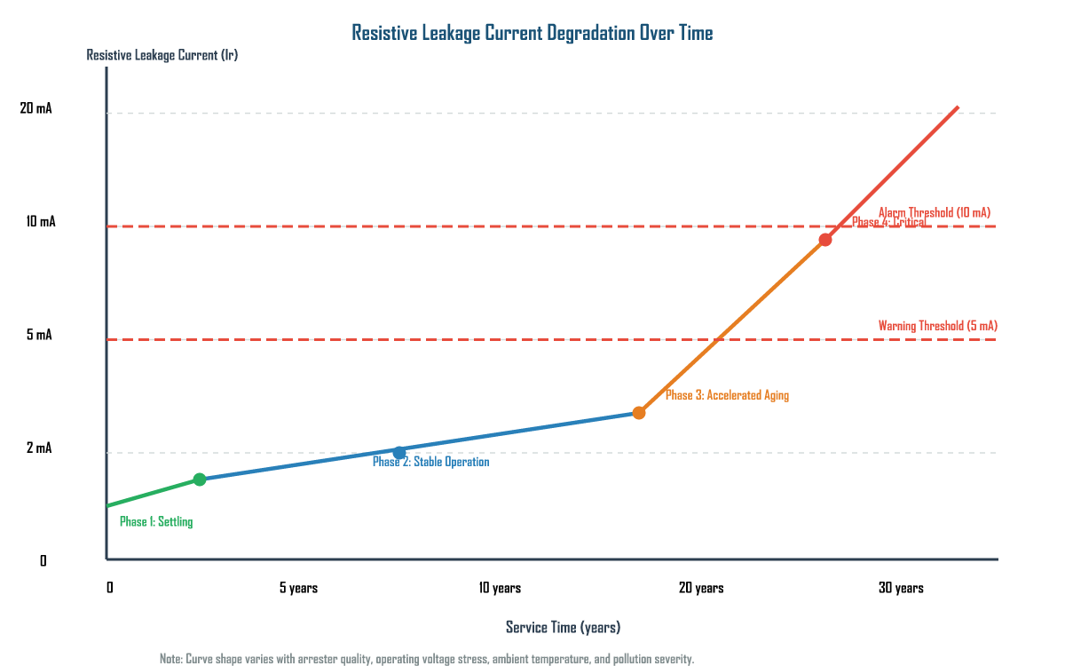
During Phase 1 (years 0–2), the resistive current may actually decrease slightly as the ZnO blocks undergo initial stabilization. Phase 2 (years 3–15) shows a very slow, nearly imperceptible increase. In Phase 3 (years 15–25), the rate of increase becomes noticeable — this is where condition monitoring becomes critical. Phase 4 represents imminent failure, where Ir rises rapidly toward thermal runaway.
Physical and Electrical Symptoms by Failure Mode
Different failure modes produce different symptom patterns. Recognizing these patterns allows maintenance teams to identify the root cause before catastrophic failure occurs:
| Failure Mode | Early Symptoms | Root Cause | Typical Time to Failure |
|---|---|---|---|
| Thermal Runaway | Increasing resistive current; housing hot to touch; elevated temperature | Sustained overvoltage; solar heating; pre-degradation; poor ventilation | Hours to days (once initiated) |
| Moisture Ingress | Decreasing insulation resistance; increased total leakage current; corrosion at seals | Seal degradation; housing cracks; O-ring failure; permeation | 2–10 years (gradual) |
| Manufacturing Defects | High initial leakage current; partial discharge; early thermal runaway | Poor ZnO formulation; contamination; improper sintering; bad sealing | < 1 year (infant mortality) |
| Pollution Flashover | Surface leakage current; audible corona; tracking marks on housing | Coastal/contaminated environment; loss of hydrophobicity; inadequate creepage | Stochastic (seasonal) |
| TOV Failure | Arrester failure following system fault; post-fault high leakage current | TOV capability not coordinated with system studies; wrong arrester rating | Sudden (during/following fault) |
| Energy Overstress | Housing rupture; internal short; complete loss of blocking capability | Lightning exceeding energy rating; capacitor bank switching surge | Sudden (during overstress event) |
| Aging Degradation | Gradual increase in resistive current; increased third-harmonic content | Long-term electrical stress; repeated surge discharges; thermal cycling | 10–25 years (end-of-life) |
Critical Warning: Thermal runaway can occur even when the applied voltage is below the rated voltage of the arrester if the arrester has pre-existing degradation (elevated leakage current) or if the ambient temperature is excessively high. A 132 kV arrester in Southeast Asia showed housing temperature rising from 42°C to 78°C over 3 months before catastrophic failure — the warning signs were present but unmonitored.
2. Root Causes: What Actually Drives Metal-Oxide Arrester Failure
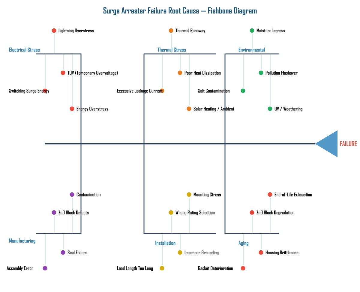
Arrester failures are never caused by a single factor in isolation. The root causes interact across six categories: electrical stress, thermal stress, environmental factors, manufacturing defects, installation errors, and aging. The fishbone diagram below maps these cause categories to their specific failure mechanisms.
Thermal Runaway — The Most Catastrophic Mode
Thermal runaway arises from the fundamental nonlinear V-I characteristics of ZnO varistor blocks. Under normal MCOV, the arrester exhibits very high resistance with only a small capacitive current (1–5 mA for distribution-class). However, the resistive component of leakage current increases exponentially with temperature. When sustained overvoltage, harmonic heating, or solar radiation raises the internal temperature, this increases the resistive current, which generates more heat. If heat generation exceeds heat dissipation, the temperature rises uncontrollably.
The mathematical condition for thermal stability is: dQgen/dT < dQdiss/dT. Once violated, the arrester temperature can rise from 80°C to over 600°C within minutes, resulting in housing rupture, expulsion of hot gases, and potentially explosive failure.
Moisture Ingress — The Leading Long-Term Degradation Mechanism
Moisture ingress is the most common long-term degradation mechanism. The internal ZnO blocks and insulating spacers are highly sensitive to moisture. When the sealing system — O-rings, gaskets, sealing compounds, and hermetic terminal seals — deteriorates, water vapor penetrates the interior. This causes: (1) surface contamination of ZnO blocks causing non-uniform current distribution; (2) corrosion of internal metal components increasing contact resistance; (3) reduction of insulation resistance; and (4) in severe cases, conductive paths leading to internal flashover.
The primary entry points are degraded O-ring seals at terminal ends, cracks in porcelain housing (from vandalism or thermal shock), failed gaskets in the base assembly, and permeation through polymer housing materials exposed to long-term UV and pollution.
Manufacturing Defects — The Infant Mortality Driver
Manufacturing defects cause premature failure even when the arrester operates within specified ratings. Common defects include:
- ZnO Block Formulation Errors: Incorrect proportion of ZnO, Bi2O3, Sb2O3, CoO, MnO, and Cr2O3 leads to non-uniform grain boundary characteristics and localized overheating.
- Incomplete Sintering: Insufficient sintering temperature or time results in poor grain boundary formation, high leakage current, and accelerated aging.
- Internal Assembly Contamination: Dust, metal particles, or moisture introduced during assembly create partial discharge sites within the column stack.
- Improper Block Grading: When ZnO blocks in a column have significantly different V-I characteristics, blocks with lower breakdown voltage carry disproportionate current and fail prematurely.
- Sealing System Defects: Inadequate sealing compound application, improper O-ring compression, or improper curing compromises long-term seal integrity.
TOV and Energy Overstress
Temporary overvoltages (TOV) are sustained overvoltages lasting from cycles to seconds, caused by single-line-to-ground faults, load rejection, or ferroresonance. IEC 60099-4 requires that a 10 kA arrester with rated voltage of 90 kV withstand 1.45 pu for 10 seconds. Failure to coordinate TOV capability with system studies is a common cause of post-fault arrester failure.
Energy overstress occurs when switching surges or multiple lightning strikes exceed the arrester’s energy absorption capability (kJ/kV of rated voltage). This is particularly common in arresters protecting capacitor banks and in areas with high ground flash density. The ZnO blocks can crack, melt, or suffer puncture under such conditions.
3. Prevention and Mitigation: Proven Strategies to Stop Failures Before They Occur
Preventing arrester failures requires a multi-layered approach: proper specification and selection, stringent quality control at procurement, correct installation practices, and a robust condition monitoring program. Each layer addresses different root cause categories identified in the fishbone diagram.
Specification and Procurement Safeguards
The first defense against failure is selecting the correct arrester for the application. This means:
- TOV coordination: Conduct system temporary overvoltage studies before selecting the arrester rated voltage. A 10-second TOV rating is insufficient if the actual system TOV lasts 30 seconds.
- Energy class matching: Select the energy absorption class based on lightning flash density (for lines) and switching surge energy (for capacitor banks). Under-rated energy class leads to block cracking during high-energy surges.
- Factory acceptance testing (FAT): Require FAT for critical station-class arresters, including residual voltage measurement, reference voltage test, and partial discharge measurement. A batch of 72 kV arresters from a new supplier was found to have sodium and potassium contaminants in the ZnO blocks — only caught through laboratory FAT.
- Supplier quality audits: Audit the ZnO varistor production process — mixing, sintering, and block grading — to ensure consistent quality.
Installation Quality Control
Studies by major utilities have shown that up to 30% of surge arrester failures can be directly attributed to installation errors. Critical installation safeguards include:
- Maintaining lead length below 1.5 m for station-class and 0.5 m for distribution-class arresters to limit inductive voltage drop during surge discharge.
- Ensuring ground resistance below 10 Ω (below 5 Ω for substations with grounded neutral systems).
- Connecting the arrester to the same ground electrode as the protected equipment to avoid ground potential rise differences.
- Using calibrated torque wrenches for all connections — under-torquing causes overheating, over-torquing damages threads and contact surfaces.
- Performing pre-installation visual inspection to reject units with housing damage, cracked porcelain, or abraded polymer housings.
Condition Monitoring and Diagnostic Program
A robust condition monitoring program is the most effective way to detect incipient failure before it becomes catastrophic. The key elements are:
Recommended Monitoring Protocol:
- Annual resistive leakage current measurement — replace arrester if Ir exceeds 5 mA (warning) or 10 mA (alarm).
- Third-harmonic analysis of leakage current for continuous online monitoring of ZnO block health.
- Biennial infrared thermography scans — compare temperatures across all three phases; a difference > 5°C indicates a problem.
- Periodic insulation resistance testing (offline) to detect moisture ingress.
- Reference voltage (U1mA) test during scheduled outages for critical station-class arresters.
Real-World Case Lessons
A utility in North America reported a 10 kV distribution arrester failure rate of 12% over 3 years in a coastal service area. Forensic analysis revealed saturated internal desiccant and water-induced corrosion of ZnO blocks — the root cause was inadequate sealing at the terminal end. After the manufacturer improved the sealing system with a secondary O-ring and low-outgassing compound, the redesigned arresters showed zero failures over 5 subsequent years in the same environment.
In another case, a 132 kV polymer-housed arrester failed catastrophically after 8 years of service following a 1.6 pu TOV for 3 seconds — the arrester’s TOV capability was only 1.45 pu for 10 seconds. Maintenance logs showed the housing temperature had been rising for 3 months (42°C to 78°C) and resistive current had increased from 1.8 mA to 8.5 mA. Both warning signs were present but unmonitored.
4. Diagnostic Methods Compared: Thermovision vs. Leakage Current vs. Partial Discharge Testing
Three diagnostic methods dominate surge arrester condition assessment: infrared thermovision, leakage current measurement, and partial discharge testing. Each method detects different failure mechanisms at different stages, and a comprehensive monitoring program should employ at least two of these complementary techniques.
| Aspect | Thermovision (Infrared) | Leakage Current Measurement | Partial Discharge Testing |
|---|---|---|---|
| Principle | Detects surface temperature anomalies using IR camera | Measures resistive component of total leakage current via CT and phase-sensitive detection | Detects internal discharge pulses indicating voids, contamination, or deterioration |
| Online/Offline | Online (energized) | Online (continuous monitoring possible) | Both (online sensors or offline lab test) |
| Sensitivity | Medium — detects thermal effects after degradation has progressed | High — detects aging, moisture, and degradation at earliest stage | High — detects internal contamination and voids before thermal effects appear |
| Best For Detecting | Thermal runaway, poor connections, uneven block degradation | ZnO block aging, moisture ingress, long-term degradation tracking | Internal contamination, manufacturing voids, seal deterioration |
| Detection Stage | Mid-to-late stage (Phase 3–4 of degradation curve) | Early stage (Phase 2–3 of degradation curve) | Very early stage (Phase 1–2 of degradation curve) |
| Threshold for Action | Temperature difference > 5°C between phases | Ir > 5 mA (warning); > 10 mA (alarm); > 50% increase from baseline | PD > 10 pC at 1.05 × MCOV (station class) |
| Limitations | Weather dependent; emissivity issues; cannot detect early-stage aging; requires line-of-sight | Requires stable voltage reference; affected by system harmonics; needs baseline data for comparison | Requires specialized equipment; background noise interference; offline test requires outage |
| Cost | Low per scan (if IR camera owned); periodic survey | Medium (online monitors); Low (portable measurement) | High (equipment + expertise); justified for station class only |
| Recommended Frequency | Biennial (annual for critical installations) | Annual (continuous for station class) | At commissioning; every 5 years; after major system events |
The optimal strategy is to use all three methods in combination: leakage current measurement for continuous online health tracking, thermovision for periodic confirmation of thermal behavior, and partial discharge testing for early detection of internal defects — especially valuable at commissioning and after major system events.
5. Summary
- Pain point: A surge arrester that fails silently during an overvoltage event leaves the entire substation exposed to catastrophic damage — and by the time visible symptoms appear, failure may already be advanced.
- Finding 1: Arrester degradation follows a predictable four-phase curve, with resistive leakage current as the most sensitive indicator. Monitoring Ir annually and acting on the 5 mA warning threshold can detect incipient failure years before thermal runaway.
- Finding 2: Six root cause categories — electrical, thermal, environmental, manufacturing, installation, and aging — interact to drive failures. Thermal runaway is the most catastrophic; moisture ingress is the most common long-term mechanism; manufacturing defects cause infant mortality.
- Finding 3: Prevention requires a multi-layered approach: TOV-coordinated specification, factory acceptance testing, correct installation (lead length, grounding, torque), and a structured condition monitoring program combining at least two diagnostic methods.
- Comparison conclusion: Leakage current measurement offers the best early-stage sensitivity and online capability; thermovision provides visual thermal confirmation; partial discharge testing detects internal defects earliest but requires specialized equipment. Using all three in combination provides the most comprehensive protection against unexpected failure.
Get Your Custom Surge Arrester Solution
Need help selecting the right surge arrester or diagnosing a field failure? Our engineering team provides free technical consultation based on your system parameters and operating environment.
Or visit www.xin-neng.com to browse our full product catalog.
About Xin-Neng Electric
Xin-Neng Electric is a leading manufacturer of high-voltage electrical equipment, specializing in surge arresters, drop-out fuse cutouts, and composite insulators for power transmission and distribution systems worldwide.
Contact: xn@xin-neng.com | www.xin-neng.com
Frequently Asked Questions
What are the most common failure modes of metal-oxide surge arresters?
Typical modes include thermal runaway, moisture ingress, housing cracking, and internal varistor degradation. These often manifest as overheating, rising leakage current, or visible housing damage.
What causes thermal runaway in surge arresters?
Thermal runaway occurs when the arrester’s internal power dissipation exceeds its ability to shed heat – usually triggered by sustained overvoltage, moisture ingress, or varistor aging that raises leakage current.
How can surge arrester failures be prevented?
Prevention combines correct rating selection, proper installation with adequate clearances, sealed end fittings, and condition-based monitoring such as thermovision, leakage-current, and partial-discharge testing.
Which diagnostic method best detects arrester degradation?
A combined approach is strongest: infrared thermography for hot spots, resistive leakage-current measurement for aging, and partial-discharge testing for internal defects. Online monitoring captures trends better than one-off offline tests.