
Poor surge arrester installation can negate the protection a correctly specified arrester is designed to provide.
Table of Contents
Key Points: What You’ll Learn
- Up to 30% of surge arrester failures can be directly attributed to installation errors — proper installation is as critical as correct arrester selection, and a single weak link compromises the entire protective function.
- Lead length minimization is paramount: the inductive voltage drop VL = L · (di/dt) adds directly to the arrester’s protective voltage. A 2-meter lead produces 20 kV of extra voltage, and a 4-meter lead caused a $1.2M transformer failure.
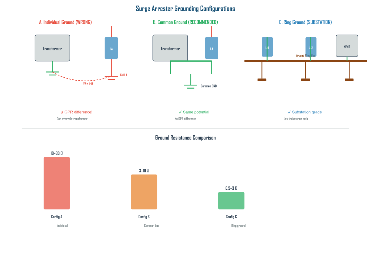
- Common grounding with the protected equipment is mandatory — separate ground electrodes create ground potential rise (GPR) differences that overvolt equipment during surges, the exact opposite of protection.
- Commissioning tests — including U1mA verification, insulation resistance, torque checks, ground resistance measurement, and infrared thermography — must be performed and documented after every installation before energization.
- Mounting method choice (pedestal vs. line post vs. suspended) directly affects lead length, grounding impedance, maintenance access, and cost — pedestal mounting is optimal for substations, line post for distribution lines, and suspended mounting should only be used as a last resort.
1. What Proper Surge Arrester Installation Involves
Proper surge arrester installation is a systematic engineering process that encompasses mounting orientation, lead length minimization, grounding configuration, torque control, clearance verification, and commissioning tests. Each element must be executed correctly — a single weak link can compromise the entire protective function. Studies by major utilities have shown that up to 30% of surge arrester failures can be directly attributed to installation errors.
Mounting Orientation
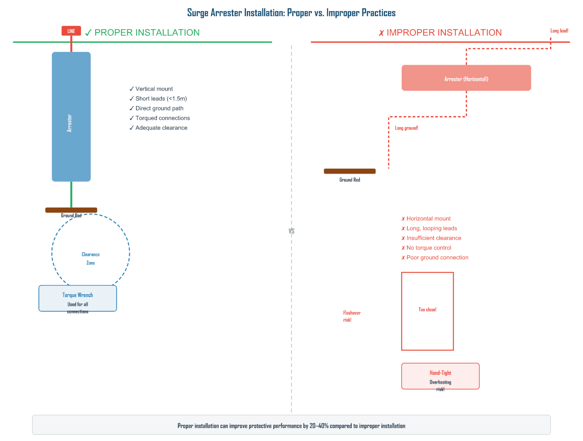
Surge arresters are designed to be mounted vertically, with the line terminal at top and ground terminal at bottom. This orientation ensures that the internal ZnO block column is under uniform compressive load from the spring-loaded stacking system. Mounting horizontally or at an angle causes uneven pressure distribution, leading to poor electrical contact between blocks, localized overheating, and premature failure.
For polymer-housed arresters, vertical mounting also ensures that water sheds (skirts) effectively shed water and prevent formation of continuous water films along the housing surface. Horizontal mounting allows water to accumulate in the sheds, promoting tracking and erosion.
Lead Length Minimization
The leads between the arrester and the protected equipment, and between the arrester and ground, must be as short as physically possible. During a surge discharge, the arrester can conduct currents of 10 kA, 20 kA, or even 100 kA. The inductive voltage drop across the lead is VL = L · (di/dt), where L is approximately 1 µH per meter and di/dt for a typical lightning surge is 10 kA/µs. A 2-meter lead produces 20 kV of inductive drop — added directly to the arrester’s protective voltage.
| Arrester Class | System Voltage | Max Lead Length (Line Side) | Max Lead Length (Ground Side) | Max Inductive Drop |
|---|---|---|---|---|
| Distribution Class | 1–36 kV | 0.5 m | 0.5 m | < 5 kV |
| Intermediate Class | 3–90 kV | 1.0 m | 0.8 m | < 10 kV |
| Station Class | 30–800 kV | 1.5 m | 1.0 m | < 20 kV |
| Very High Energy (VHE) | 100–800 kV | 2.0 m | 1.5 m | < 30 kV |
Grounding Configuration
The grounding system is the most critical part of the installation. A surge arrester cannot protect anything if the surge current cannot be effectively dissipated into the earth. Key requirements include:
- Ground resistance: Less than 10 Ω for most applications; less than 5 Ω for substations with grounded neutral systems (preferably less than 1 Ω for 400 kV+ stations).
- Common ground electrode: The arrester must connect to the same ground electrode as the protected equipment to avoid ground potential rise (GPR) differences that can overvolt the equipment during a surge.
- Ground lead material: Copper or copper-clad steel is required. Aluminum must not be used for buried ground connections due to galvanic corrosion risk.
- Connection method: Exothermic welding is preferred for permanent ground connections. Mechanical connectors must be listed for the application and properly torqued.
Clearance and Torque Control
Minimum phase-to-ground and phase-to-phase clearance distances must comply with IEC 60099-4 or IEEE C62.11. At high altitudes (>1000 m), clearance must be multiplied by the altitude correction factor. Connection torque values must follow manufacturer specifications — typically 40–80 N·m for station-class line terminals and 40–60 N·m for ground terminals. A calibrated torque wrench is mandatory; “feel” is not acceptable.
2. Why Installation Quality Directly Determines Protection Performance
The protective performance of a surge arrester is not defined by the arrester alone — it is defined by the complete installed system including leads, ground path, and connections. Even the highest-rated, most advanced arrester will fail to protect equipment if installation quality is compromised. The following diagram illustrates the critical differences between proper and improper practices:
The Real Cost of Excessive Lead Length
A real-world example demonstrates the consequences: a 145 kV substation installed station-class arresters with 4-meter line-side leads instead of the recommended <1.5 m. During a lightning strike, the induced voltage across the leads was measured at 85 kV, raising the voltage at the transformer terminals to 620 kV — well above the transformer’s BIL of 550 kV. The transformer suffered a winding failure that cost $1.2 million to repair.
Consequence: Excessive lead length renders the arrester ineffective by adding inductive overvoltage to the protection voltage. The protected equipment sees Varrester + L·(di/dt), which can exceed equipment BIL even though the arrester itself is operating correctly.
Grounding: Why Common Grounding Matters
Connecting the arrester to a different ground electrode than the protected equipment creates a ground potential rise (GPR) difference during surge discharge. The arrester ground potential can rise above the equipment ground, effectively applying an overvoltage to the equipment — the exact opposite of protection. The grounding configuration diagram below illustrates three approaches:
Commissioning: The Final Verification
After installation, a systematic commissioning process must verify that the arrester was not damaged during installation and all connections are properly made. The commissioning checklist includes:
| Check Item | Acceptance Criterion | Method | Criticality |
|---|---|---|---|
| Arrester rating verification | Rated voltage ≥ system MCOV × 1.25 | Review nameplate and system study | Critical |
| Mounting orientation | Vertical ± 5° from plumb | Spirit level | High |
| Line-side lead length | ≤ 1.5 m station; ≤ 0.5 m distribution | Measure with tape | High |
| Connection torque | Per manufacturer spec (40–80 N·m station) | Calibrated torque wrench | Critical |
| Ground resistance | ≤ 10 Ω (≤ 5 Ω substation) | 3-point fall-of-potential test | Critical |
| Insulation resistance (offline) | > 10,000 MΩ station; > 1,000 MΩ distribution | 5 kV megger test | Medium |
| Reference voltage (U1mA) | Within ± 5% of nameplate | DC reference voltage test | High |
| Infrared thermography | No phase temperature difference > 5°C | IR scan after energization | Medium |
3. Installation Best Practices Across Different Application Environments
Installation practices must be adapted to the specific application environment — what works for a distribution pole may not work for a 400 kV substation or a GIS compartment. The following scenarios cover the most common installation environments encountered by utilities and industrial facilities.
Overhead Distribution Lines (1–36 kV)
On overhead distribution lines, arresters are typically installed on poles at transformer locations, at the ends of feeders, and at regular intervals along the line for lightning protection. Key practices include:
- Mount the arrester directly on the pole or crossarm, as close to the phase conductor as possible.
- Keep the line-side lead shorter than 0.5 m — use a rigid connector if possible instead of flexible cable.
- Connect the ground lead directly to the pole ground wire with an exothermic weld or listed connector.
- For transformer protection, mount the arrester on the load side of the fuse cutout so that a failed arrester trips the fuse rather than causing a sustained outage.
- Maintain minimum 200 mm clearance from the pole surface to prevent tracking.
Substation Station-Class Installations (30–800 kV)
In substations, station-class arresters are installed as close as physically possible to the transformers and other critical equipment. Key practices include:
- Use rigid bus connections (copper or aluminum tubing) instead of flexible cable leads to minimize inductance and mechanical movement.
- Mount on dedicated pedestal structures with reinforced concrete foundations.
- Connect to the substation ground grid (not a separate ground rod) — grid resistance must be < 1 Ω for 400 kV+ stations.
- Install lightning surge counters on all three phases for monitoring.
- For GIS installations, use GIS-integrated arrester modules or wall-mounted polymer arresters with short gas-insulated bus connections.
Capacitor Bank Protection
Capacitor banks generate high-energy switching surges that can exceed the energy rating of standard arresters. Special considerations:
- Use arresters with energy class 5–10 kJ/kV or higher, specifically rated for capacitor bank switching duty.
- Install arresters phase-to-ground on both the line side and the bank side of the switching device.
- Consider phase-to-phase arresters for banks where phase-to-phase switching surges are a concern.
- Verify that the arrester’s energy absorption capability exceeds the calculated bank stored energy (½CV²).
Industrial and High-Pollution Environments
In coastal, industrial, or desert areas, pollution flashover is a major concern. Installation practices should include:
- Use polymer-housed arresters with silicone rubber insulation for superior hydrophobicity and pollution performance.
- Specify extended creepage distance (at least 31 mm/kV for heavy pollution per IEC 60815).
- Install at least 300 mm above ground level to prevent salt spray contamination of the lower sheds.
- Schedule periodic cleaning (hot water washing) for porcelain-housed arresters in heavy pollution zones.
- Consider installing leakage current monitors with pollution alarm thresholds in severe environments.
Universal Best Practice: Regardless of application environment, always (1) minimize total lead length, (2) use common grounding with protected equipment, (3) apply calibrated torque to all connections, (4) verify clearance distances, and (5) perform and document commissioning tests. A completed installation checklist should be archived for every arrester installed.
4. Mounting Methods Compared: Pedestal vs. Line Post vs. Suspended Installation
The mounting method selected for a surge arrester affects mechanical stability, lead length, maintenance access, and cost. The three most common mounting methods — pedestal, line post, and suspended — each serve different applications and have distinct advantages and limitations.
| Aspect | Pedestal Mount | Line Post Mount | Suspended Mount |
|---|---|---|---|
| Typical Application | Substations (station class, 30–800 kV) | Distribution lines, riser poles (1–69 kV) | Transmission towers, limited-access structures (69–500 kV) |
| Mounting Structure | Dedicated steel or concrete pedestal on foundation | Bolted directly to wooden or concrete pole | Suspended from crossarm or tower member via insulator chain |
| Orientation | Vertical (optimal for ZnO block compression) | Vertical (optimal) | Inverted or angled (requires manufacturer approval) |
| Lead Length (Typical) | 0.5–1.5 m (short, rigid bus possible) | 0.3–1.0 m (short, direct to phase wire) | 1.0–2.5 m (longer due to suspension geometry) |
| Grounding Path | Direct to ground grid via pedestal (lowest impedance) | Down pole ground wire (low impedance) | Through structure/tower (moderate impedance) |
| Mechanical Stability | Excellent — rigid foundation, no sway | Good — stable on pole, slight vibration possible | Moderate — wind-induced sway, mechanical stress on connections |
| Maintenance Access | Excellent — ground-level access, easy IR scanning | Good — climbable pole, bucket truck access | Poor — requires tower climb or crane, difficult IR scanning |
| Cost (Structure + Installation) | High (foundation + pedestal fabrication) | Low (simple bracket hardware) | Medium (suspension hardware + insulator chain) |
| Inductive Voltage Drop | Lowest (short rigid leads, low inductance ground path) | Low (short leads, direct ground) | Highest (longer leads, indirect ground path) |
| Best Suited For | Transformer protection in substations; equipment BIL coordination | Overhead line protection; distribution transformers | Retrofit on existing towers; limited ground space situations |
| Key Risk | Foundation settling can misalign arrester over time | Pole deterioration can compromise mounting stability | Wind sway fatigues electrical connections; inverted mounting may void warranty |
For most substation applications, pedestal mounting provides the best combination of short leads, low grounding impedance, and maintenance access. Line post mounting is the standard for distribution-level overhead protection. Suspended mounting should only be used when pedestal or line post mounting is physically impossible, and only with arresters explicitly qualified by the manufacturer for inverted or angled installation.
5. Summary
- Pain point: Poor installation can negate the protection a correctly specified arrester is designed to provide — up to 30% of arrester failures trace directly to installation errors.
- Finding 1: Proper installation involves five interdependent elements: vertical mounting, minimized lead length, common low-resistance grounding, calibrated torque on all connections, and verified clearance distances. Any single weak link compromises the system.
- Finding 2: Installation quality directly determines protection performance because the protected equipment sees Varrester + L·(di/dt) — excessive lead length and poor grounding add voltage that can exceed equipment BIL even when the arrester operates correctly. A 4-meter lead caused 85 kV of extra voltage, destroying a $1.2M transformer.
- Finding 3: Best practices must be adapted to the environment: rigid bus connections for substations, pole-mounted distribution arresters with fuse coordination, high-energy-class arresters for capacitor banks, and polymer housings with extended creepage for polluted areas.
- Comparison conclusion: Pedestal mounting offers the shortest leads and best grounding for substations; line post mounting is cost-effective and standard for distribution; suspended mounting is a last resort with the highest inductive drop and maintenance difficulty. Choose the method that minimizes lead length and maximizes grounding effectiveness for each application.
Get Your Custom Surge Arrester Solution
Need help selecting the right surge arrester or planning a proper installation? Our engineering team provides free technical consultation based on your system parameters and site conditions.
Or visit www.xin-neng.com to browse our full product catalog.
About Xin-Neng Electric
Xin-Neng Electric is a leading manufacturer of high-voltage electrical equipment, specializing in surge arresters, drop-out fuse cutouts, and composite insulators for power transmission and distribution systems worldwide.
Contact: xn@xin-neng.com | www.xin-neng.com
Frequently Asked Questions
What does proper surge arrester installation involve?
It includes correct mounting (pedestal, line post, or suspended), secure bonding to ground, adequate separation from the protected equipment, and verification of torque and insulation clearances per the design.
Why does installation quality affect protection performance?
Poor installation – such as weak grounding, excessive lead length, or proximity issues – increases lead inductance and the protection distance, raising the overvoltage actually seen by the equipment and defeating the arrester.
What are the main mounting methods for surge arresters?
Pedestal (base-mounted), line post (vertical post), and suspended (hung) installations. The choice depends on switchgear type, available space, and mechanical load.
What should be checked during surge arrester commissioning?
Verify the correct rating, measure insulation resistance, confirm grounding continuity, ensure fittings are secure, and inspect for transport damage before energization.