Project Description
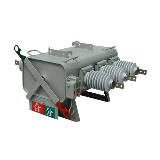
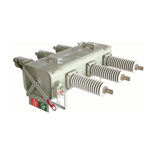
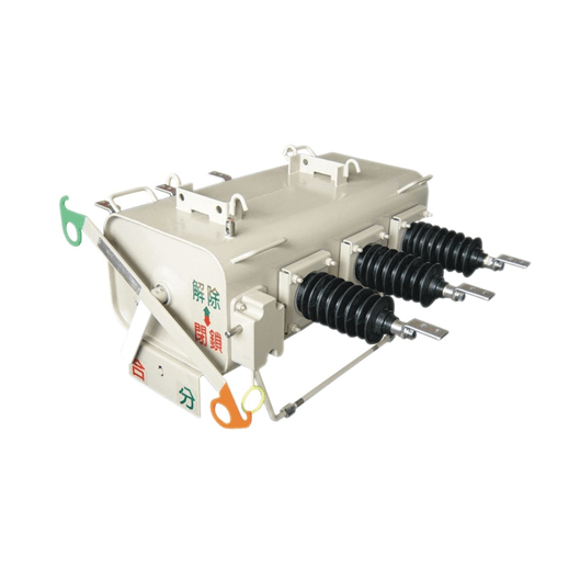
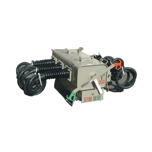
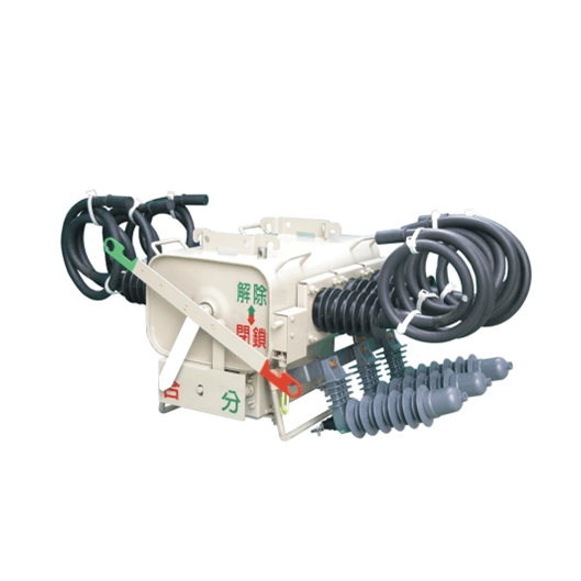
Pole Mounted 11/24/33kV SF6 Load Break Switch
Description:
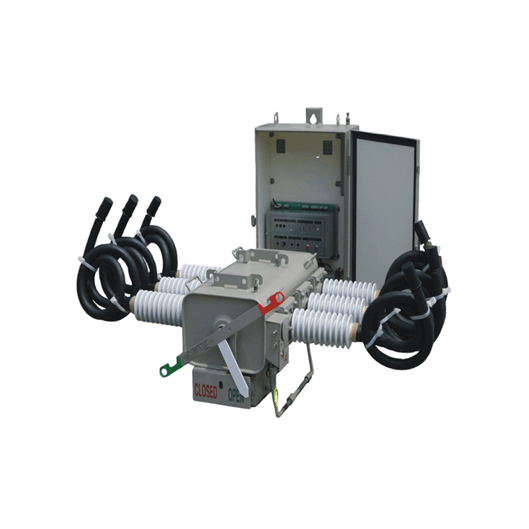
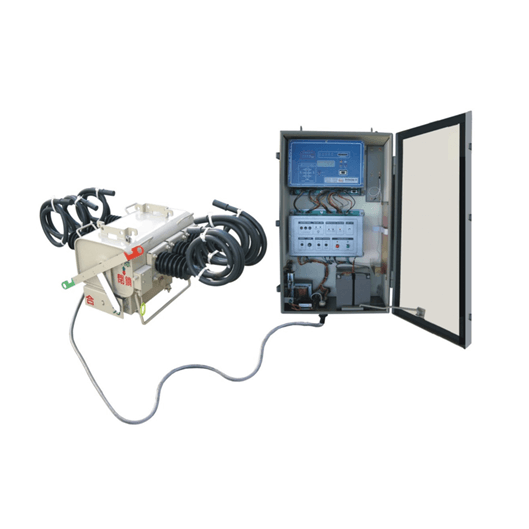
Pole mounted SF6 load break switch is used for rated voltage 12/24/40.5KV, Rate current 400/630A, 50/60Hz distribution system. There are two types – manual operated and motor operated with remote control cabinet. The electronic controller could be installed inside the steel chamber, so it could be used in various climate conditions.
Besides that, the wire/wireless modem installed inside control cabinet could achieve remote monitoring and controlling. It’s easy and convenient for installation on single pole.
1. Standards
IEC 60056: High Voltage alternating current load break switches.
IEC 60376: Specification and acceptance of new sulfur hexafluoride.
IEC 144: Degree of protection of enclosures for low voltage switch gear and control gear.
BS 5311: Specification for A.C. load break switches of rated voltage above 1 kV.
IEC62271-103, GB/T3804: 3.6-40.5KV AC high voltage load break switch.
2. Operating conditions
The Load Break Switch is suitable for continuous outdoor operation in tropical areas with the following atmospheric characteristics:
(a) Altitude: 2200m above means sea level
(b) Pollution: Heavy saline atmosphere
(c) Humidity: Up to 90%
(d) Ambient temperatures of +30℃ average (+40℃ Max. and -1℃ Min.)
(e) Isokeramic level: Up to 180 thunderstorm days.
3. Construction
(a) The load break switch is three pole operated, out-door type, SF6 gas insulated and comply with the requirements of IEC 60056 and/or BS 5311.
(b) All the three poles are interconnected by a suitable shaft, linked to the operating mechanism so that poles are operated simultaneously with common gas pressure monitor.
(c) All the three poles of load break switch are operated by local electrical from the mechanism in the housing and remote electrical from remote panel.
(d) The mechanism box shall have a mechanical facility for manually operating the three poles.
(e) The load break switch have SF6 gas for electrical interrupting medium.
(f) The SF6 gas complies with the requirement of IEC 60376 and is suitable for use in the load break switch when it is operated under the service and system conditions.
(g) Sufficient gas provided for filling the load break switch at installation with additional 20% for any losses.
(h) When the load break switch is in closed position a rapid fall in the SF6 gas pressure, to a level below that at which safe operation is possible do not result in tripping the load break switch. A remote alarm indication to signal this condition is provided.
(i) Insulation creepage distance is more than 25mm per kV of maximum operating voltage between phases.
4. Operating Mechanism
(a) The operating mechanism is suitable for mounting at the load break switch supporting structure, and below the load break switch in a weather-proof, dust- proof, vermin-proof and well ventilated housing.
(b) The degree of protection is class IP 54 as per the requirement of IEC 144.
(c) The housing is provided with padlocking facility.
Operating mechanism is trip free during the entire closing sequence.
(a) Operating mechanism is provided with motor wound spring charging mechanism with provision for hand operated manual charging.
(b) The Motor is universal with operating voltage of either 110 Volts DC or 110 Volts AC.
SF6 load break switch is provided with Local/Remote selector switch. The selection of the local operation is inhibit the operation of the load break switch from any remote source.
(a) The load break switch closing circuit is blocked in case the SF6 gas pressure drops below the allowed operational value.
(b) Two spare contacts are provided from the gas relay for alarm and blocked state indications. These spare contacts are wired up to the terminal block.
5. Load break switch is provided with a local switch for Open/Neutral/Close operation.
(a) Mechanically operated indication to show the status of the load break switch operations (open/close and springs charged/discharged) are provided.
(b) The load break switch is provided with suitable terminals for connecting tinned copper tubes.
(c)The load break switch is provided with means to prevent contact pumping should the circuit be energized while tripping command is issued.
(d) Mechanical interlock arrangement is provided on the mechanism such that it is not possible to withdraw the interlock with load break switch in closed position.
6. Guaranteed technical parameters for Pole Mounted Load Break Switch
| # | Description of Parameters | Unit | Value | ||||
| 1 | Rated voltage | KV | 12 | 24 | 40.5 | ||
| 2 | Rated frequency | Hz | 50/60 | 50/60 | 50/60 | ||
| 3 | Rated insulation level
(Filled SF6 gas 0.07MPa) / (at 20 ℃) |
Lightning impulse withstand voltage | Phase to phase | KV | 75 | 125 | 185 |
| Fracture | 85 | 145 | 215 | ||||
| Power frequency withstand voltage
1min |
Phase to phase | KV | 42 | 64 | 90 | ||
| Fracture | 50 | 79 | 95 | ||||
| 4 | Insulation level at zero gauge pressure | Power frequency withstand voltage for 1min | KV | 30 | |||
| Reverse phase withstand voltage for 1min | 30 | ||||||
| Maximum phase voltage 5min | 9 | ||||||
| 5 | Rated current | A | 630 | 630 | 630 | ||
| 6 | Rated breaking load current (0.05Mpa / at 20 ℃) | A | 630 | 630 | 630 | ||
| 7 | Breaking current under zero gauge voltage | A | 630 | 630 | 630 | ||
| 8 | Peak withstand current | KA | 50 | 50 | 50 | ||
| 9 | Rated short-time making current | KA | 50 | 50 | 50 | ||
| 11 | Rated short-time withstand current | KA/s | 20/4 | 20/4 | 20/4 | ||
| 12 | Rated cable charging breaking current | A | 25 | 25 | 25 | ||
| 13 | Rated charging line breaking current | A | 16 | 16 | 16 | ||
| 14 | Rated closed-loop breaking current | A | 630 | 630 | 630 | ||
| 15 | Exciting current | A | 21 | 21 | 21 | ||
| 16 | Rated current breaking times | second | ≥400 | ≥400 | ≥400 | ||
| 17 | Rated working pressure | MPa | 0.05 | 0.07 | 0.1 | ||
| 18 | Main circuit resistance of each phase | μΩ | ≤150 | ≤150 | ≤150 | ||
| 19 | Relative gas leakage rate | year | ≤1% | ≤1% | ≤1% | ||
| 20 | Moisture content of SF6 gas | Factory handover value | PPM | ≤150 | ≤150 | ≤150 | |
| Switch operating value | PPM | ≤300 | ≤300 | ≤300 | |||
| 21 | Mechanical stability operation | second | 6000 | 6000 | 6000 | ||
| 22 | Rated operating voltage and rated voltage of auxiliary circuit | V | DC 220/
110/48/24 |
DC 220/
110/48/24 |
DC 220/ 110/48/24 |
||
| AC 220/110 | AC 220/110 | AC 220/110 | |||||
| 23 | Weight | Type M | Kg | 115 | 125 | 135 | |
| Type A | 135 | 145 | 155 | ||||
| 24 | Protection grade of mechanism box and controller | IP44 | |||||
Video will be updated soon.

